|
|
|
Fiber Optic Multiplexor FMUX-4
(stand-alone model)
Discontinued, recommended replacement is: FMUX/M, FMUX/S
Specifications
Optical Transceiver Parameters
Documentation
 |
Features:
|
FMUX 4E1 is a multiplexor for transmitting 4 E1 channels over the fiber optic link. All channels have independent sync signals with their own frequencies.
The device has optional channel (Ethernet 10Base-T or V.35/RS-530/RS-232/X.21). With this option box models have 3 E1 channels and one optional channel, rack mount models have 4 E1 channels and one optional channel (console configurable 4 E1 or 3 E1 + optional channel modes).
Models with Ethernet 10Base-T port support VLAN protocol.
FMUX has LEDs for channels ready state, optic transceiver operability, loopbacks enable state and test mode indication. Internal loopbacks and integral BER tester operation are controllable by the console port located on front panel or by switches. BER tester meters bit error rate in optic link using permanent or pseudo random code in compliance with the ITU-T O.151 Recommendation (test sequence length equals to 215-1=32767 bits).
Device state can be monitored by SNMP using separate Ethernet 10Base-T port.
Remote device management is available by remote login feature. Service data exchange is supported by additional service channel using same optic link.
Alarm indication relay with "dry contacts" interface in compliance with the ITU-T G.742 Recommendation, paragraph 10, is supplied.
The firmware of the device can be updated by user.
Currently available models are listed in Prices. Please, contact technical support if you are unsure which model to choose.
| Interface E1 (2048 kbit/sec) | |
|---|---|
| Connector Type | RJ-48 (female 8 pins) |
| Line Code | HDB3 |
| Framing | Transparent; both framed and unframed modes supported |
| Error Detection | Bipolar Violation |
| Line Impedance | 120 Ohm (Twisted Pair) |
| Receive Signal Attenuation Range | From 0 to -36 dB |
| Input Signal Measurement | Precision 2 dB |
| Jitter Attenuator | In transmit path |
| Overvoltage Protection | TVS |
| Overcurrent Protection | Fuse |
| Interface Ethernet | |
| Interface | 10Base-T |
| Connector Type | RJ-45 (female) |
| Data rate | 2048, 1024, 512, 256, 128 or 64 kbit/sec |
| Mode | 10 Mbps Full-duplex, or 10 Mbps Half-duplex |
| Address table size | 15000 MAC addresses |
| Maximum packet size | 4224 bytes, including MAC header |
| Protocols | Transparent or Cisco-HDLC bridging IEEE protocol, automatically selected |
| Quality of Service | 8 priority levels |
| Alarm Interface | |
| Connector Type | 6 Pins Mini-DIN |
| Relay Contact Current | Up to 250 mA |
| Relay Contact Voltage | Up to 100 VDC |
| Control interface | |
| Connector Type | RS-232 DCE, DB-9 (female) |
| Protocol | Asynchronous, 9600 bit/sec, 8 bit/symbol, 1 stop bit, no parity |
| Modem Control Signals | DTR, DSR, CTS, RTS, CD |
| Diagnoctic modes | |
| Loopbacks | Local, Remote |
| BER Tester | Built-in |
| Control | By switches on front panel or via control port RS-232 |
| Physical | |
| Dimensions | 200 mm x 260 mm x 65 mm |
| Weight | 1100 g |
| Power source | |
| AC power source | 176-264 V, 50 Hz |
| DC power source | 36-72 V |
| Power | 20 VA Max |
| Environment | |
| Temperature | 0° - 50°С |
| Humidity | 0 to 80 %, non-condensing |

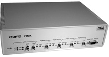
![]() FMUX-4 with four E1 ports (desktop)
- User's Manual in Russian
FMUX-4 with four E1 ports (desktop)
- User's Manual in Russian
![]() FMUX-4 with three E1 ports and one Ethernet 10Base-T port (desktop) - User's Manual in Russian
FMUX-4 with three E1 ports and one Ethernet 10Base-T port (desktop) - User's Manual in Russian
![]() MIB-files for SNMP-management
MIB-files for SNMP-management
Return to Fiber Optic Modems and Multiplexors or Digital Communication Equipment
Copyright © 1996-2026 Cronyx